In my previous post, I wrote very briefly about an important improvement to the irradiance caching algorithm – irradiance gradients – and I’m going to expand on rotational gradients this time.
Gradients
The gradient of a function represents both the direction and rate of change of that function as the inputs vary. For a one dimensional function this is simply the derivative of the function. As you move into higher dimensions, you need to consider which coordinate system the inputs for the function are specified in, as this will change how you need to calculate the gradient.
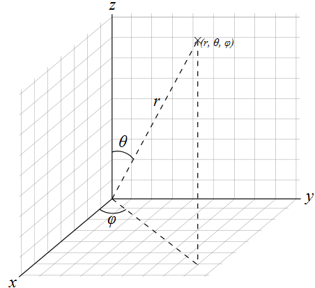
For now, I’m just going to focus on calculating the gradient of a function defined using normalized spherical coordinates. Unfortunately, there’s no real standard way to define spherical coordinates, and despite similar looking symbols, the values are often interchanged. I’m going to define the spherical coordinates on the unit sphere as azimuthal value φ [0, Ï€), and polar value θ [0, 2Ï€).

When dealing with multiple dimensions, you can calculate the gradient by splitting the gradient calculation into multiple partial derivatives and summing them with appropriate vector weights. For normalized spherical coordinates the gradient is:
The function f represents a scalar field, so the gradient is a vector field. Each vector points in the direction of greatest increase. Much like the integrals of functions described using spherical coordinates, you have to take care to weight the azimuthal contribution by the sine of the polar angle.
As a real-world example of using gradients, let’s calculate the gradient for a simple function:
The derivatives of the function for each argument are easy to calculate:
Combining these together with the previous definition, you can calculate the gradient vector at any point on the unit sphere for f using:
There’s lots more to be learned about gradients, and a good start would be Wikipedia, and also this page on the MIT website.
Rotational Irradiance Gradient
The irradiance contribution from a direction on the hemisphere about the surface normal, specified using spherical coordinates φ [0, 2π) and θ [0, π / 2) is:
Where L is the incident radiance in the supplied direction. So to calculate the gradient vector at any point on the hemisphere, you just need to evaluate:
This just calculates the gradient in a specific direction, but for the irradiance gradient we need to calculate the average gradient over the entire hemisphere. We can do this at the same time as we calculate the irradiance by using a similar Monte Carlo estimator. We want to share the sampling strategy between the irradiance calculation and the rotational gradient calculation, so we’re stuck using the same pdf:
So the estimator for the irradiance gradient becomes:
Which collapses down to:
The vector v is a unit vector on the plane of the hemisphere pointing in the perpendicular direction to the angle φ. There are two perpendicular vectors to φ, and which one you decide to use depends on the order you do the cross product on when evaluating the gradient. Using the left hand rule for rotation, I’m doing a clockwise rotation of φ by ninety degrees.
Using the Rotational Irradiance Gradient
The irradiance estimate at a point is defined by a weighted sum of irradiance cache entries:
Now we have the rotational gradient, we can use it to improve the estimate. The cross product of the surface normal and cache entry normal represents both a direction and magnitude of rotational difference. We then project this difference onto the irradiance gradient to calculate how much the irradiance is changing in that direction:
Note that conceptually this calculation needs to be performed once for each color channel, since the gradient of the irradiance is really the gradient of three scalar fields – red, green and blue. In practice it’s easier to assume that the gradient is a three dimensional vector of colors, rather than scalars.
Implementation
The implementation is pretty straightforward, but there are a couple of optimizations that can be made because we are using a unit hemisphere for sampling. Assuming that we have the sample direction in Cartesian coordinates in local space, where the z-axis points in the polar direction, we can get the cos weighting from the z coordinate:
Also, we can get the sine weighted projected unit vector by simply setting the z value to zero, since:
So, to get the local space tan weighted perpendicular vector, we just need to use the following:
Note that the x and y values were swapped, and the x value negated to get the perpendicular vector.
Results
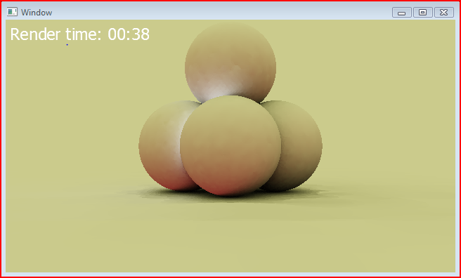
I’ve rendered out a before and after shot, showing just the indirect irradiance. There are no translational gradients being used at the moment, so there are still some artefacts. Here’s the before shot:

And here’s the same render, but with rotational gradients this time:

Note that the time to render each frame is almost exactly the same, yet the rotational gradients provide a much smoother result. Next I’ll implement translational gradients and hopefully the image will look considerably better.
Hi
I like your blog a lot. If I was to recommend one thing that would improve your IC images, I’d suggest simply using more neighbours when you interpolate. I know Ward is happy to extrapolate an irradiance from only 1 sample in the cache, but it’s much more common to use the nearest N. Your images will get a lot nicer, fast!
Happy New Year
Neil
Thanks for the tip. I’ll definitely try it out and post the results.
[…] Finally, Rory Driscoll provides a good introduction from a programmer’s point of view: part 1, part 2. […]