| Warning: This post is going to be pretty math heavy. If you suck at math, then go and read this first, then come back. If you still think that you suck, then I suggest going to Khan Academy and start watching videos. You won’t regret it! |
I was reading through the AMD CubeMapGen source last week and came across the code for calculating the solid angle of a cube map texel. This code piqued my interest, since it seemed very terse for what I thought would be a horrific calculation.
static float32 AreaElement( float32 x, float32 y )
{
	return atan2(x * y, sqrt(x * x + y * y + 1));
}

float32 TexelCoordSolidAngle(int32 a_FaceIdx, float32 a_U, float32 a_V, int32 a_Size)
{
   //scale up to [-1, 1] range (inclusive), offset by 0.5 to point to texel center.
   float32 U = (2.0f * ((float32)a_U + 0.5f) / (float32)a_Size ) - 1.0f;
   float32 V = (2.0f * ((float32)a_V + 0.5f) / (float32)a_Size ) - 1.0f;

   float32 InvResolution = 1.0f / a_Size;

	// U and V are the -1..1 texture coordinate on the current face.
	// Get projected area for this texel
	float32 x0 = U - InvResolution;
	float32 y0 = V - InvResolution;
	float32 x1 = U + InvResolution;
	float32 y1 = V + InvResolution;
	float32 SolidAngle = AreaElement(x0, y0) - AreaElement(x0, y1) - AreaElement(x1, y0) + AreaElement(x1, y1);

	return SolidAngle;
}
The source code for this particular part is well documented, and points you towards this thesis by Manne Öhrström (@manneohrstrom) where he gives a high level overview of the derivation. I was interested in finding out some more of the details, so I had a go myself, and this post is the result.
Why is it Useful?
When processing cube maps (for example, generating a diffuse irradiance map, or spherical harmonic approximation), you need to be able to integrate the texel values over a sphere.
One way of approximating this integral is to use a Monte Carlo estimator. This is a statistical technique that may oversample some texels and undersample other. This seems a bit wasteful considering that we have a finite number of input values. Ideally we’d like to use each texel value just once.
A naive approach to analytical integration where each texel has the same weight would result in overly bright values in the corner areas. This is because the texels in the corners project to smaller and smaller areas on the sphere. The correct approach is to factor in the solid angle during the integral, and this is what CubeMapGen does.
The Plan
Imagine a single cube map face placed at (0,0,1) and scaled such that the texel locations are all in [-1,1]. For any texel in this cube map, we want to project it onto a unit sphere sitting at the origin, then work out the area on the sphere. This area corresponds to the solid angle because the sphere is a unit sphere.
We can repeat this same calculation for any of the other cube map faces by first transforming them into the same range.
This is the high-level game plan for calculating out the solid angle:
- Determine a formula for projecting a position from texture-space onto the sphere.
- Work out how this projected position changes as the texture-space coordinates change in x and y.
- Imagining that these position change vectors define two sides of a microscopic quadrilateral, then calculate the microscopic area of this quad using the magnitude of the cross product.
- Integrate the microscopic area using the corner coordinates of a texel to calculate its area on the sphere, and solid angle.
The Details
We start off with the formula for projecting a point from its location on the texture face (x, y, 1) onto the unit sphere. This is just a standard vector normalization.

|
Note: I’ll be switching back and forth between negative and fractional exponents as I see fit. This makes things easier. Remember, |
We want to calculate how this projected point changes as the texture-space x and y coordinates change. We can do this separately for each axis using partial derivatives. First we’ll start by calculating how the projected z component changes along to the texture-space x axis.
Projected Z Change According to X
The z-component of p is simply:

We need to differentiate this equation with respect to x. Because of the exponent, we need to use the chain rule to do this. The chain rule is a method for finding the derivative of the composition of two functions. First, we can reformulate the equation a little bit to make the two functions a bit clearer:
![]()
In our case our first function is a function of ![]() and our second function is a function of
and our second function is a function of ![]() and
and ![]() . Given this, the chain rule says:
. Given this, the chain rule says:
![]()
We can apply this rule very easily to our reformulated functions:
![Rendered by QuickLaTeX.com \begin{align*} \frac{\partial p_z}{\partial u} &=-\frac{u^{-\frac{3}{2}}}{2}\\ &=-\frac{1}{2(x^2+y^2+1)^{\frac{3}{2}}} \\[10] \frac{\partial u}{\partial x}&=2x\\[10] \frac{\partial p_z}{\partial x} &= -\frac{x}{(x^2+y^2+1)^{\frac{3}{2}}} \end{align*}](https://www.rorydriscoll.com/wp-content/ql-cache/quicklatex.com-ae0b2428e50b1171daec7bafca098554_l3.png)
This equation tells us exactly how the z component of the projected point changes as the texture-space position moves along the x axis.
Projected X Change According to X
Now we’ve found the projected z component derivative, it’s going to make finding the x and y components a little easier. Why? Because we can express the x and y components in terms of the z component.

We don’t have the same ‘composition of functions’ setup that we did last time, so we can’t use the chain rule to differentiate this. Instead, we can use the product rule. The product rule in our case says:
![]()
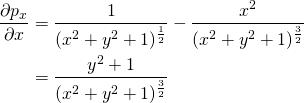
Applying this to equation for for the projected x component:

Projected Y Change According to X
We have a very similar derivation for the projected y derivative:
![]()
We can use the product rule again:

Projected Position Change According to X and Y
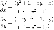
Putting this all together, we have our equation showing how the projected position changes as the texture-space position changes in the x direction. We can use the exact same process to work out how it moves in the y direction.

Differential Area
The next step is to calculate the differential (microscopic) area of the projected point using the partial derivatives we just calculated. Clearly at a normal scale, we wouldn’t be able to take the cross product of two projected vectors on a sphere and expect the magnitude to be the area they define on the sphere. But at this differential scale, we can treat the surface as if it is flat, so this works.
The first thing we need to do is to calculate the cross product of the partial derivatives.

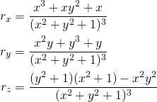
Calculating the cross product for each of the components relatively straightforward.

If you’re reading carefully, you’ll notice that each component has a factor of ![]() on the top and the bottom, so we can divide through. Combining all the components back together again, we arrive at the final equation for the perpendicular vector.
on the top and the bottom, so we can divide through. Combining all the components back together again, we arrive at the final equation for the perpendicular vector.
![]()
Now we simply need to take the length of the result of the cross product to find the differential area on the sphere.
![Rendered by QuickLaTeX.com \begin{align*} \partial A &= \sqrt{\vec{r} \cdot \vec{r}}\\[5] &= \sqrt{\frac{x^2+y^2+1}{(x^2 + y^2+1)^4}}\\[5] &= \frac{1}{(x^2 + y^2+1)^{\frac{3}{2}}} \end{align*}](https://www.rorydriscoll.com/wp-content/ql-cache/quicklatex.com-d01ca9cd76b91c518393ab4a9ad617bf_l3.png)
Solid Angle
The final step is to integrate the differential area over our range of texture-space values to get the solid angle of the texel. We can start by calculating the integral between ![]() and some point
and some point ![]() on the cube map face.
on the cube map face.

From this formula, we can calculate the area of any texel in the cube map face by adding together the two right-diagonal corners, A and C, and subtracting the left-diagonal corners, B and D.
![]()
You can see on the image below that the added areas in green are canceled out by the subtracted areas in red.
That should look familiar, since that’s exactly what the CubeMapGen code does. If you look at the surrounding source code to TexelCoordSolidAngle, then you’ll notice that there’s another method mentioned for calculating the solid angle of a texel. This method is based on Girard’s theorem, which describes how to calculate the area of a spherical triangle based on the excess of the sum of its interior angles. This method was also suggested to me on Twitter by Ignacio Castaño (@castano). I haven’t actually tried it, but it looks fascinating!
Is it Correct?
It’s always a bit daunting to get to the end of a derivation like this, and not know if the answer is correct or not. In this case, it’s pretty easy to verify if this result is correct.
Remember that the texture-space coordinates are in range [-1,1]. If we set our ![]() values to 1, that corresponds to the top right quarter of the cube map face. We know that there are
values to 1, that corresponds to the top right quarter of the cube map face. We know that there are ![]() steradians in a sphere, so that means that each face gets
steradians in a sphere, so that means that each face gets ![]() steradians. Since we’re only calculating for a quarter of a face we expect our result to be
steradians. Since we’re only calculating for a quarter of a face we expect our result to be ![]() .
.

And it does. Thanks to the various people on twitter (@SebLagarde, @mattpharr, @manneohrstrom, @castano and @ChristerEricson) for engaging me in conversation over this.
Please let me know in the comments if you spot an error in this post, or if anything needs to be explained better or more easily.


I did a different derivation for this a long time ago when I first had to do projection for SH. I think it’s a little simpler.
I’d post the derivation for it here in the comments but I put it on google wave and lost all my documents when I didn’t pay attention to them closing up shop. If you want I can post a full derivation.
The high level sketch of the derivation is,
Given a spherical-coordinate on the unit sphere, (\theta, \phi), find the projected coordinate in polar coordinates on the top cube face (r,t). First find the mapping r(\theta, \phi), t(\theta, \phi). From calculus we know the differential area of a sphere surface is sin(\phi) d\phi d\theta and we also know the differential area of a surface in polar coordinates is r d\r d\t, then we can take our new mapping r(\theta, \phi), t(\theta, \phi) plug it into our differential and find the scaling factor from the projection.
From symmetry we can find all other faces and integration is simple.
-= Dave
Here is some quick LaTeX I whipped up of the above description. I don’t know if comments accept images so I’ll put the source as well. Basically, the 1/cos(phi)^3 is the scaling factor between the area on the sphere and projected area.
The only other tricky part is recognizing that cos(phi) is L – the length of line from the origin to the cartesian coordinate of the texel.
Looks like they don’t accept html images 🙁 Sorry!
I edited your comment to put the latex tags around the math. Thanks for the alternate derivation.
I also had a go at the Girard’s theorem derivation, but it really didn’t come out much simpler. Girard’s theorem itself is very nice, but calculating the angles of the spherical triangle turned out to be a bit of a mess. I didn’t put too much time into it though, so I daresay there’s a simpler way to calculate the angles than I did.
I’ve actually used spherical triangles in the past to allow arbitrary meshes to be quickly projected onto spherical harmonics. E.g. if artists want to paint a mesh in Maya to be used as area lighting.
http://www.whim.org/nebula/math/pdf/spheretrig.pdf
Lot of good easy to digest info in that document. I don’t think I’d use it for cube map convolution w/ a brdf though. I like the 1/L^3 formula as its pretty simple.
That’s a nice idea to be able to project arbitrary meshes like that. Was that used in any games?
I actually used the formula in section 9 (L’Huilier’s Formula) to calculate the texel area when I had a go. It felt like it could be simpler when added to the arc length calculation for the sides of the triangle.
[…] [7] Discroll, “Cubemap Texel Solid Angle” http://www.rorydriscoll.com/2012/01/15/cubemap-texel-solid-angle/ Advertisement LD_AddCustomAttr("AdOpt", "1"); LD_AddCustomAttr("Origin", "other"); […]
Unfortunately, the code hasn’t made its way to a shipped game yet. Maybe in the future we can have this conversation again.
I can say that the artists preferred throwing a cube in Maya, tessellating it, painting the vertices with their paint tool and seeing the lighting change in realtime over painting a cube map in photoshop. It also allows them to do things like light the cube via light sources or whatever else their imagination comes up with.
-= Dave
@David: Very Cool! Yeah, what’s nice about expressing light as an SH coefficient is that it such a compact description of a spherical signal! And since it is an L^2 basis, it blends nicely, both temporally and spatially and as overlays – back in 2003 when I wrote my thesis we also built tools so that artists could paint on cube maps and add artificial light to scenes – we also precomputed light in the scene by baking SH coeffs and sprinkling them around the scene. Light was then applied to dynamic objects by adding the static precomputed lights with the hand edited effects-lights. It is quite cool, especially when animated over time. And it is high dynamic range too – back in the day that was a big deal. 🙂
@Manne, Yah it is a lot of fun. I’m sad I didn’t read your paper when I originally did a lot of this work, skimming it now seems like you did good work. We did a lot of similar things from what you said as well.
I’m now of the opinion that I prefer high quality static bakes over the low frequency dynamic lighting solutions SH can offer. This is my opinion of course, but I’d rather wait 10 seconds for a high quality bake then iterate on low frequency solutions.
Anywhoo, things change all the time so maybe I’ll be singing a different tune in a year. Good work regardless!
And rory, I really enjoy the math heavy blogs, keep them coming 🙂
-= Dave
Hey Rory,
Peter-Pike presents a simplified version in his “Stupid SH Tricks” paper. He takes the integral of (1+s^2+t^2)-(3/2) over [-1..1]. Wolfram Alpha tells me that “integrate 1/(1+x^2+y^2)^(3/2) dx dy, x=-1..1, y=-1..1” equals 4Pi/6, which makes sense, each face of the cube map takes a sixth of the area of the surface of the sphere. [if we summed all little areas of texture coordinates on -1 to 1].
Because for a low number of discrete steps, the final sum won’t quiet be 4Pi, Peter-Pike normalizes the final result to 4Pi. The resulting code looks quite simple. No arctan in sight!
Hey Rory,
Peter-Pike presents a simplified version in his “Stupid SH Tricks” paper. He takes the sum of 4.0/(1 + s^t + t^2)^(3/2) for each texel s and t in the range [-1 .. 1] and normalizes the result at the end by multiplying by 4Pi/Sum(all weights). The resulting code looks quite simple. No arctan in sight!
-djg
Here’s a bit of python code as proof of concept:
http://www.pastebin.com/dHk7w9Rs
Hi,
in case of GPU radiosity is a better idea to calculate the solid angle as these calculations or just use a texture as explained here?
http://freespace.virgin.net/hugo.elias/radiosity/radiosity.htm
i was searching practical information about solid angles for other mappings (ex. spherical, dual paraboloid) but there’s not much fully explained in the internet.
I’ve found something in the source code from Chapter 10 of GPU Gems 2 (see BuildTextures.cpp if interested) about dual paraboloid projection and the cubemap one of course
http://developer.nvidia.com/node/28
do you know any book or link that could help me? Or could you make some extra post about it? 😉 I know they are not good projections in certain situations but i’d to experiment anyway and possibly try something like this one
http://www.youtube.com/watch?v=Z9u8EdFbmiI
Thanks
The texture in the link you sent looks like a precomputed version of what I outlined in this article, so it’s perfectly fine to use it.
I’m afraid I haven’t even thought about other mappings, though I’m sure others have. I haven’t look, but I would imagine that the ‘Physcally Based Rendering’ book might have some information on this.
Hello, I believe you have a typo in one of the steps. Right after the cross product, shouldn’t the expoent at the bottom be ^3? It’s what I always get, and it checks out with the rest of the article after I divide the polynomials.
Yes, thanks for pointing that out. I’ve fixed it now.